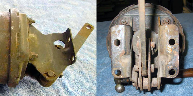
Finding the brake pedal ratio for most vehicles is easy enough with a tape measure and calculator. The hardest part is usually getting the tape up under the dashboard where the upper pivot of the brake pedal and pushrod mount. But certain brake setups (Like the booster at top from a 1966 Ford Mustang) require more measuring and extra math because of a second lever and pivot, commonly called a bell crank.
On Wilwood's Pedal Remote Master Cylinder Mount with adjustable balance bar, it works the opposite way. The force from the pedal is multiplied and increased when fed into the balance bar and dual master cylinders.
The math is relatively easy to figure out once you know there is a second set of measurements and a second step to the calculations. Below is a typical example.
Power Brake Booster Bell Cranks

Back when power brakes were merely optional on most cars, and unboosted four-wheel-drum brakes were the rule, some vacuum boosters were mounted on an offset bracket, inches away from the firewall. There were several reasons for this. For one, it streamlined production on the assembly line, as it made installing a brake booster as easy as installing the unboosted master cylinder; there was no need to have another worker inside the car tightening nuts. Secondly, it moved the rather large booster up and away from the steering column and valve cover on V8-powered vehicles. Lastly, there was no need for a different ratio brake pedal assembly inside the cockpit.
Some think the vacuum booster bracket mounting it up and away from the firewall is just there to make everything fit better. But, no, on many of these cars there is a second lever arm built into the bracket which lowers the brake pedal ratio. Without it, the brakes become touchy and over boosted with vacuum assistance.
Typically in a bell crank system, a lever pivots at the bottom of the mount, with the pedal attaching 2/3rds up and the pushrod on top for a 1:1.5 ratio, reducing the overall ratio by 33%. A factory 6:1 pedal ratio attached to the bell crank results in a 4:1 ratio going into the power booster, in most cases. (The exact numbers for each application are different. The numbers in this example were used to make the math simpler.)
Bell crank brackets are standard with power brakes on cars like early Ford Mustangs, 1959-64 full-size Chevy and other GM cars, and 60s Mopars. The original Ford Broncos mounted the booster and master cylinder at an angle, pointing 45 degrees away from the firewall, making more room for the engine. You can still buy exact duplicates of most of these or universal versions, making it easy to add a power brake booster without drilling extra holes or changing pedals.
Eventually, General Motors engineers came up with an easier solution, though not straightforward, and stopped using the bell crank. If you have ever wondered why the booster and master cylinder are angled up slightly on some cars, with the front higher than the back, that was their solution. By angling the booster and pushrod they provided two different pedal ratios with the same brake pedal by drilling a second, lower hole. The only downside (besides aesthetics) is that the slanted mounting means bench bleeding before installation is essential to avoid trapped air in the master cylinder.
Wilwood Remote Balance Bar System

The bell crank on Wilwood's 60 Degree Mount Pedal and Remote Tru-Bar Pedal works the opposite way, increasing the pedal ratio of the pedal connected to it. A bell crank is connected to your pedal, with the balance bar connected between it and the pivot point. This increases your mechanical advantage by about 1.5:1 (and actually increasing through the length of the pedal stroke) over the master cylinder pistons, at the same time increasing pedal travel. This is especially helpful, since a balance bar system splits your leg effort between two master cylinders.
When connected to one of these Wilwood bell crank balance bars, a typical 6:1 pedal gets an effective ratio of 9:1. A 5:1 pedal becomes a 7.5:1 ratio. If you have a tight cockpit without a lot of room for a large ratio brake pedal, like in a Midget or Sprint car, these remote mounts are genuine problem solvers. They allow two remote-reservoir master cylinders to mount stacked, one above the other, to fit tight engine compartments.
Either of these remote mount balance bars provides the other significant benefit of a balance bar pedal; they allow fine-tuning of brake bias between two separate master cylinders, often in different bore sizes.
For those unfamiliar with the concept of a balance bar, they are mostly used in top levels of racing. A smaller bore master cylinder connected to the front calipers paired with a larger bore for the rear provides much greater control of the front to rear brake bias. The adjustment knob on the balance bar allows the bias to be further fine-tuned from the cockpit during the race to account for changing track conditions or lightened fuel load.


Beñny,
I had to google the 1957 Buick, and I must say that is one of the most complicated pedal linkage arrangements I have ever seen. Fortunately when looking for images of the linkage, I also found the reprint of the factory service manuals at HometownBuick.com. According to the original GM manual, the manual brakes result in a 6:1 ratio, and “…the 1957 Buick power brake linkage is approximately 1 ½ to 1.” The wording there is confusing, but being familiar with other GM bell crank systems, I believe that means the linkage reduces the 6:1 manual pedal to a 4:1 (4 × 1 ½ = 6). This is right in the typical range we see for most cars from the 950s thru the 1980s.
If you want to measure and confirm yourself, my suggestion would be to start with a simplified version of the picture from the Buick manual and add measurements. Then just do the math for each series of pivots.
How do I find brake pedal ratio as the 57 Buick has a belt crank on the pedal assembly not on the master cylinder how do I calculate it if I want to change it also